When a Mixing Tank Motor Trips at 2 AM — And Nobody Knows Why
In process-intensive textile manufacturing — dyeing lines, chemical mixing, sizing machines, compressor drives — an unplanned motor trip is rarely just an electrical fault. It is a batch ruined, a downstream conveyor starved, a compressor offline during a critical curing cycle. The real problem is not the trip itself. It is the invisibility: a standalone thermal overload relay trips at 2 AM, the motor cools down, somebody resets it at 6 AM, and the root cause — persistent phase voltage imbalance, a slowly degrading bearing drawing excess current — is never investigated.
That invisibility is exactly what the UBZ-302 and UBZ-304 numeric motor protection relays from Novatek Electro are engineered to eliminate. Both devices carry on-board Modbus RTU communication, structured fault history logging, and remote parameter configurability — transforming motor protection from a passive trip device into an active node in your plant SCADA architecture.
This article goes deep: the physics of motor protection, how these relays actually process current and voltage signals, key parameters you need to set correctly, a head-to-head comparison, wiring best practices, and the FAQs that engineers ask us before signing a purchase order.
The Physics Behind the Protection: What the Relay Is Actually Measuring
A three-phase induction motor is extraordinarily sensitive to two families of electrical disturbance: voltage-quality events (overvoltage, undervoltage, phase loss, phase sequence reversal, phase imbalance) and current-quality events (overload, locked rotor, phase-to-phase current imbalance). Each failure mode follows a distinct thermal or electromagnetic signature.
Thermal Inverse-Time Overload Model
The stator winding temperature rise follows an exponential function of I²t — current squared times time. A motor running at 120% of rated current does not fail instantly; it accumulates heat. The relay implements a thermal memory model that tracks this I²t integral continuously, even across power cycles. This is why the UBZ-302 and UBZ-304 enforce a restart inhibit timer after a thermal trip: the winding must cool before re-energisation, preventing the cumulative damage that repeated hot-starts inflict on Class F or Class H insulation.
Phase Loss and Imbalance Detection
Single phasing — loss of one supply phase while the motor is running — causes the remaining two phases to carry the full three-phase current load. Stator current in the healthy phases can exceed 1.73× rated value within seconds. The relay detects this by comparing the three line-current RMS values continuously. When the imbalance ratio crosses the programmed threshold, the relay trips on phase-current asymmetry faster than the thermal model would, because the thermal model alone is too slow for single-phasing events on lightly loaded motors.
Voltage Window Monitoring
Both relays monitor supply voltage continuously across a nominal operating window of 320 V to 480 V AC (suitable for 380–415 V motor systems). Undervoltage below the set lower threshold causes the relay to trip, because reduced voltage forces the motor to draw proportionally higher current to maintain torque, accelerating winding heating. Overvoltage above the upper threshold increases iron losses and magnetising current. The relay enforces both limits with programmable thresholds and independent response-time delays.
UBZ-302: Built-in CTs, Modbus, SCADA-Ready Motor Protection
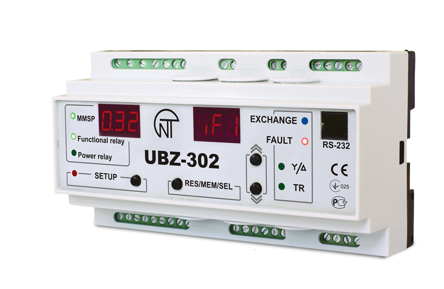
The UBZ-302 is a three-phase numeric motor protection relay with built-in current transformers, making it directly insertable on motor feeders up to 63 A without external CTs. For larger motors, it connects to external CTs, covering the full programmable range of 5 A to 630 A. The protection envelope covers motors from 2.5 kW to 315 kW on 380–415 V systems.
Protection Functions — UBZ-302
- Three-phase overload with inverse-time thermal model and thermal memory
- Phase loss and phase current asymmetry
- Phase sequence (rotation) protection
- Overvoltage and undervoltage (320–480 V window)
- Phase voltage imbalance
- Locked rotor / stall protection
- Restart inhibit (configurable cool-down timer)
- No-load / underload detection (pump dry-run protection)
SCADA Integration via Modbus RTU
The UBZ-302 carries an RS-485 Modbus RTU port. From any SCADA or DCS host — Wonderware, Ignition, Vijeo Citect, or a PLC acting as Modbus master — you can read live current values per phase, supply voltage, thermal state percentage, trip cause code, and fault history log. You can also write protection parameters remotely: change the overload set-point for a different motor without pulling the relay or opening the panel. For a textile plant running multiple product recipes that alter motor loading patterns, this remote configurability is operationally significant.
Price: Rs. 15,742 per piece (ex-GST). GST @ 18% applicable extra.
Buy UBZ-302 OnlineUBZ-304: Numeric Protection with Modbus at a Tighter Budget Point
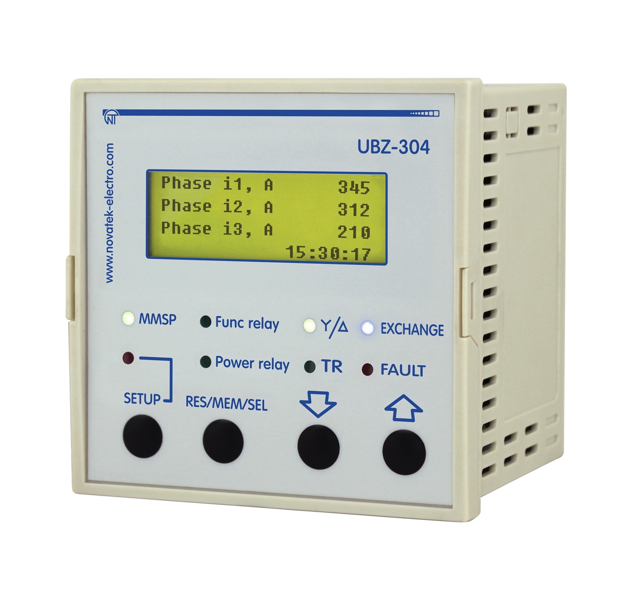
The UBZ-304 is the numeric LT motor protection device in this family, covering the same power range (2.5–315 kW) and voltage window (320–480 V), with a programmable current range of 5 A to 630 A. Its output is an SPDT relay (1NO + 1NC), suitable for contactor control circuits. Like the UBZ-302, it supports Modbus RTU communication and structured fault logging.
The UBZ-304 is particularly well-suited to conveyor drives and mixing tank motors where external CTs are already installed as part of the motor control centre (MCC) design, and where the panel builder needs SCADA connectivity at the lowest possible per-feeder cost.
Price: Rs. 10,550 per piece (ex-GST). GST @ 18% applicable extra.
Buy UBZ-304 OnlineModel Comparison: UBZ-302 vs UBZ-304
| Parameter | UBZ-302 | UBZ-304 |
|---|---|---|
| Type | Three Phase Motor Protection (with built-in CTs) | Numeric LT Motor Protection |
| Motor Power Range | 2.5 – 315 kW (4 – 500 HP) | 2.5 – 315 kW (4 – 500 HP) |
| Motor Voltage | 380 – 415 V AC | 380 – 415 V AC |
| Operating Voltage Window | 320 – 480 V AC | 320 – 480 V AC |
| Programmable Current Range | 5 A to 630 A | 5 A to 630 A |
| Built-in CTs (direct connection) | Yes, up to 63 A | External CTs required |
| Phase Configuration | 3 Pole, 4 Pole | 3 Pole, 4 Pole |
| Output Relay | Functional SPDT | SPDT (1NO + 1NC) |
| Modbus RTU Communication | Yes (RS-485) | Yes (RS-485) |
| Fault History Logging | Yes | Yes |
| Remote Parameter Configuration | Yes (via Modbus) | Yes (via Modbus) |
| Application Sweet Spot | MCC feeders up to 63 A direct; larger via ext. CTs | MCCs with existing CT infrastructure |
| Price (ex-GST) | Rs. 15,742 | Rs. 10,550 |
Quick Selection Guide: Application vs Recommended Model
| Application | Motor Size (Typical) | Recommended Model | Price (ex-GST) |
|---|---|---|---|
| Chemical reactor agitator | 11–45 kW | UBZ-302 | Rs. 15,742 |
| Mixing tank drive (up to 63 A) | 7.5–30 kW | UBZ-302 (built-in CTs) | Rs. 15,742 |
| Fabric conveyor drive | 5.5–22 kW | UBZ-304 | Rs. 10,550 |
| Compressor drive (MCC with ext. CTs) | 37–200 kW | UBZ-304 + external CTs | Rs. 10,550 |
| SCADA-integrated MCC (multiple feeders) | Mixed fleet | UBZ-302 (small feeders) + UBZ-304 (large feeders) | Mix as applicable |
| Dyeing machine pump motor | 3.7–18.5 kW | UBZ-302 | Rs. 15,742 |
Wiring Best Practices for Textile Plant MCCs
RS-485 Bus Topology
Wire the Modbus RS-485 network as a daisy-chain bus, not a star. Use twisted-pair cable (Belden 9841 or equivalent, 120 Ω characteristic impedance). Terminate the bus at both physical ends with 120 Ω resistors — most Modbus masters have a built-in termination switch. In a textile plant MCC room with 20–40 motor feeders on a single RS-485 segment, maintain the total cable length within 1,200 m for reliable 9,600 baud communication. For longer runs or noisy environments, use RS-485 repeaters.
CT Polarity and Burden
For UBZ-304 installations using external CTs, verify CT polarity (P1→P2 primary, S1→S2 secondary) before energising. Reversed CT polarity causes the relay to misread current direction and may prevent correct phase-imbalance detection. CT burden must be matched to the relay input impedance — do not use 15 VA CTs with a relay that expects 5 VA; the excess burden causes ratio error and protection inaccuracy.
Control Circuit Isolation
The relay output contacts (SPDT) should control the contactor coil circuit, not the main power circuit directly. Always use a control-circuit fuse (2 A HRC) in series with the relay output. For SCADA alarm outputs, use the NC contact wired to the SCADA DI module with a normally-energised scheme — a relay power failure then appears as an alarm, not a silent condition.
Troubleshooting Common Installation Issues
Relay Trips Immediately on Motor Start
Most commonly caused by the overload set-point being programmed to rated current without accounting for starting current. During direct-on-line starting, induction motors draw 5–7× rated current for 3–8 seconds. Set the start-inhibit (starting time) parameter to cover the actual acceleration period of your driven machine. For high-inertia loads like compressors, this may be 10–15 seconds.
Modbus Registers Not Responding
Verify: (1) Each relay on the bus has a unique Modbus address. (2) Baud rate, parity and stop-bit settings on relay match the SCADA master configuration exactly. (3) RS-485 bus termination is present at both ends. (4) Cable shield is grounded at one end only (SCADA panel end) to avoid ground loops. (5) The relay is powered — Modbus communication is inactive if the relay has no supply voltage.
Nuisance Trips on Phase Imbalance
In textile plants, large motor starts on adjacent feeders can cause transient voltage dips that create momentary current imbalance. If the phase-imbalance trip delay is set too short (under 1 second), these transients cause nuisance trips. Increase the phase-imbalance response delay to 2–3 seconds while keeping the voltage monitoring response fast for sustained faults.
Why Novatek Electro?
- ISO 9001:2015 Certified Manufacturing: Every device is built and tested under a documented quality management system — not assembled from unverified components.
- CE Certified Products: UBZ-302 and UBZ-304 carry CE marking, confirming compliance with European LVD and EMC directives — relevant for textile exporters supplying to EU markets who require CE-compliant machinery documentation.
- Made in India — Delhi-Based Manufacturer: Domestic manufacturing means shorter lead times, rupee-denominated pricing insulated from forex volatility, and accessible after-sales support.
- 30+ Years of Electrical Protection Engineering: Novatek Electro has been developing protection relays for industrial applications for over three decades — the product designs reflect accumulated field learning, not first-generation prototypes.
- Technical Support and Documentation: Detailed datasheets, connection diagrams, Modbus register maps, and application notes are available. Pre-sales technical consultation is available through authorised distributors and direct inquiry.
UBZ-302 (Rs. 15,742 ex-GST) and UBZ-304 (Rs. 10,550 ex-GST) are available for immediate dispatch through our authorised distribution network across India.
Order online at intelli-electro.com — or contact our technical sales team:
Email: sales@novatek-electro.in
Phone: +91-7840054744
Shop Motor Protection Relays