When Your Solar Plant's Maximum Demand Charge Undercuts Its Green Savings
Here is the uncomfortable reality that every electrical engineer managing a solar or renewable energy installation eventually confronts: your utility's maximum demand charge is calculated on a 15-minute or 30-minute sliding window — and a single momentary surge from a compressor start, pump kick-in, or auxiliary load can push your recorded demand into a higher tariff slab for the entire billing month. The irony is sharp. You have invested in rooftop solar or a grid-tied renewable system specifically to reduce energy costs — yet the demand component of your bill, driven by unmanaged peak loads, quietly erodes those savings every month.
Demand-side management (DSM) at the panel level is the engineering answer. And it does not require a SCADA system or a building energy management server. With the right overload relays and power controllers — specifically the Novatek Electro OM-310, OM-163, and RMT-101 — your distribution panel becomes an intelligent load-shedding node that protects circuits, enforces demand limits, and conserves energy without operator intervention.
The Physics Behind the Problem: Why Peak Demand Is So Destructive
Maximum demand is not simply 'how much power you use' — it is the highest averaged power draw recorded in any demand interval within the billing period. Under Indian electricity tariff structures (IS 12360, CEA regulations), industrial and commercial consumers on HT and LT tariffs are billed a demand charge in Rs./kVA or Rs./kW for their recorded maximum demand, regardless of how briefly that peak occurred.
In a solar-integrated facility, the problem is compounded: when solar generation drops suddenly (cloud transient, dust soiling, inverter trip), the grid suddenly sees the full site load. If non-critical loads — HVAC zones, water heating, auxiliary pumps, lighting banks — are not automatically shed at that moment, the demand spike is recorded and billed. A relay with a programmable demand window and a contactor-drive output is the only cost-effective way to automate this shedding at the panel level.
Simultaneously, reactive power drawn by motors and inductive loads degrades power factor. Most utilities penalise power factor below 0.90 (lagging) or 0.85, and reward correction above 0.95. An integrated power controller that monitors kVAR in real time and drives capacitor bank contactors closes this loop without a separate APFC relay.
The OM-310: Three-Phase Demand Controller and Overcurrent-Earth Fault Relay
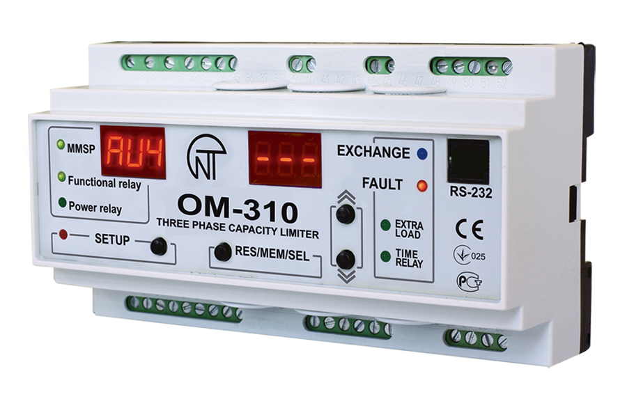
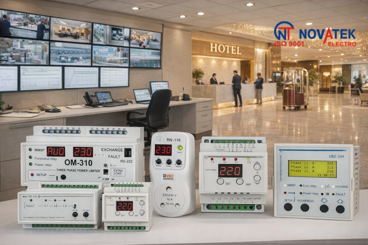
The OM-310 is Novatek Electro's flagship numeric, multi-functional demand controller for three-phase installations. It operates across a supply voltage window of 380–415 V AC and covers a current (and therefore power) range of 5 A to 800 A (2.5 kW to 450 kW) — making it suitable for everything from a 5 kW rooftop solar auxiliary panel to a 450 kW grid-tied commercial solar plant's main incomer.
What the OM-310 Actually Does in a Solar Panel
- Demand Controlling: Monitors real-time active power consumption and executes complete load rejection (all non-critical contactors tripped) when consumption exceeds the main threshold for a user-set time delay. It also executes partial load rejection — a staged, priority-based shedding sequence — when consumption exceeds an intermediate threshold. This graduated response prevents nuisance tripping while still protecting the demand window.
- Overcurrent Protection: Independent overcurrent trip with programmable pickup and time-delay curves. Functions as a complement to — not a replacement for — the upstream MCCB.
- Earth Leakage Protection: Detects earth fault current through a summation CT, critical for solar installations where DC ground faults can propagate into the AC distribution network.
- Voltage Monitoring: Monitors phase voltages and trips on under/over-voltage — relevant where solar inverter output fluctuations affect downstream load voltages.
- Output Contacts: 1 × SPDT programmable contact (1NO + 1NC) for signalling/alarm, plus 1 × DPDT power contact (2NO + 2NC) for direct contactor driving. Potential-free outputs suit both PLC integration and standalone wiring.
The OM-310 is available at Rs.15,687 per piece (ex-GST). For a three-phase solar-integrated industrial panel handling 100 kW+ of connected load, this is the relay of choice.
Buy OM-310 OnlineThe OM-163: Single-Phase Power Controller for Distributed Solar Sub-Panels
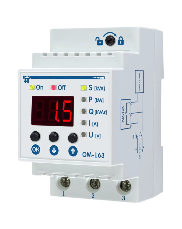
Not every load management decision happens at the main incomer. In solar installations, single-phase sub-panels feed office lighting, HVAC terminal units, water heaters, and EV charging points — all of which are prime candidates for demand shedding without affecting production. The OM-163 is designed precisely for this tier.
Operating on single-phase (2-pole) AC supplies from 130–300 V, rated to 63 A at 250 V AC, the OM-163 monitors and displays total power (kVA, up to 14 kVA range), active power (kW), reactive power (kVAR), current consumption, and mains voltage — all on its 3-digit LED display. It functions simultaneously as:
- A power controller / limiter — trips or signals when the set kW or kVA threshold is breached
- A voltage monitor — detects under/over-voltage on the single-phase supply
- An energy meter — real-time power parameter display reduces the need for a separate sub-meter
- An overcurrent relay — independent current-based protection
The OM-163 is powered directly by the circuit feeding the load — no separate auxiliary supply required. This matters in solar installations where auxiliary power availability during inverter transitions is not guaranteed.
At Rs.3,500 per piece (ex-GST), the OM-163 is arguably the most cost-effective demand controller available for single-phase sub-panel applications across residential solar, commercial rooftop, and agricultural solar pump systems.
Buy OM-163 OnlineThe RMT-101: Current Overload Relay for Motor-Load Shedding Circuits
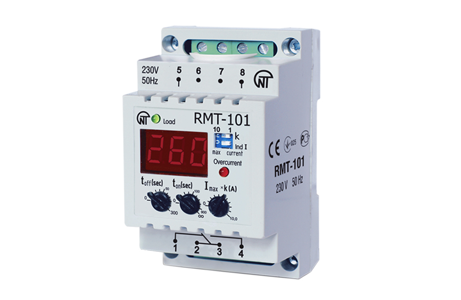
Where the OM-310 and OM-163 manage power (kW/kVA), the RMT-101 manages current. It is a dedicated current overload relay that executes load rejection when current exceeds a settable threshold from 0 to 100 A. Key ratings: nominal insulation voltage 450 V, rated impulse withstand voltage 2.5 kV, pollution degree II, overvoltage category II, IP40 device enclosure.
In renewable energy panel-building, the RMT-101 is deployed as the contactor-driving protection relay for individual motor loads — cooling fans, pumps, tracking actuators — within a solar plant's auxiliary system. Its current setpoint is dialled to match the motor's full-load current (FLC), and it trips the motor contactor on sustained overload. At Rs.5,475 per piece (ex-GST), it is the economical choice for motor-level protection where a full power controller is not warranted.
Buy RMT-101 OnlineModel Comparison: OM-310 vs OM-163 vs RMT-101
| Parameter | OM-310 | OM-163 | RMT-101 |
|---|---|---|---|
| Phase Configuration | 3-Phase / 4-Phase | Single-Phase (2-pole) | Single (current sensing) |
| Voltage Range | 380–415 V AC | 130–300 V AC | Up to 450 V (insulation) |
| Current / Power Range | 5 A–800 A (2.5–450 kW) | Up to 63 A @ 250 V (14 kVA) | 0–100 A (settable) |
| Display | Dual LED numeric | 3-digit LED + indicators | LED indicators |
| Demand Control | Yes (partial + complete) | Yes (power limiter) | Current-based trip only |
| Earth Fault Protection | Yes | No | No |
| Voltage Monitoring | Yes | Yes | No |
| Energy Metering | Yes (kW, kVA, kVAR, A, V) | Yes (kW, kVA, kVAR, A, V) | No |
| Output Contacts | 1×SPDT + 1×DPDT (potential-free) | Relay output | Relay output (contactor drive) |
| Impulse Withstand | — | — | 2.5 kV |
| Price (ex-GST) | Rs.15,687 | Rs.3,500 | Rs.5,475 |
Quick Selection Guide: Application vs Recommended Model
| Application Type | Recommended Model | Price (ex-GST) | Reason |
|---|---|---|---|
| Grid-tied solar plant main incomer (3-phase, >10 kW) | OM-310 | Rs.15,687 | 3-phase demand control, earth fault, OC, voltage monitoring |
| Commercial rooftop solar sub-panel (single-phase) | OM-163 | Rs.3,500 | Power limiting, energy metering, voltage monitoring in one |
| Agricultural solar pump motor protection | RMT-101 | Rs.5,475 | 0–100 A settable overload, contactor-drive output |
| Wind/solar hybrid auxiliary motor loads | RMT-101 | Rs.5,475 | Per-motor overload protection, 2.5 kV impulse withstand |
| Solar plant demand management + billing optimisation (LT tariff) | OM-310 + OM-163 | From Rs.3,500 | Hierarchical shedding: main incomer + sub-panel level |
| Residential/small-scale solar net-metering (single-phase) | OM-163 | Rs.3,500 | Compact, self-powered, displays kW/kVA/kVAR on 3-digit LED |
How the Circuit Works: Panel-Level Load Shedding Architecture
A typical solar panel-level DSM circuit using the OM-310 works as follows. A set of current transformers (CTs) on each phase feeds the OM-310's current inputs. The relay continuously computes three-phase active power. When measured kW exceeds the programmed demand threshold — say, the contracted demand limit — for longer than the user-set time delay, the OM-310's DPDT power output contact opens, de-energising the contactor coil of the lowest-priority non-critical load (HVAC, water heater, etc.). The SPDT programmable contact simultaneously sends an alarm signal to the SCADA or BMS. If power drops below the threshold, the relay can be programmed to auto-reclose after a restoration delay, restoring the shed load. Staged (partial) shedding trips only an intermediate-priority load when an intermediate power threshold is crossed, reserving complete rejection for genuine demand ceiling breaches.
For single-phase sub-panels, the OM-163 mirrors this logic within its 130–300 V, 63 A operating envelope, and adds real-time energy parameter display — eliminating the need for a separate sub-metering device on each feeder.
Wiring Best Practices for Solar Installations
- CT sizing: Select CTs with a 5 A secondary and rated primary matching the feeder's FLC. For the OM-310 covering 800 A circuits, use 800/5 A accuracy class 0.5 CTs to preserve measurement accuracy for demand calculation.
- CT burden: Keep total CT secondary wiring burden within the CT's rated VA. Long cable runs between CT and relay increase burden and introduce metering error — use adequate cross-section (1.5 mm² minimum for CT leads).
- Separate auxiliary supply: The OM-310 should be powered from a dedicated MCB-protected auxiliary supply, not the CT secondary. Confirm auxiliary voltage matches the supply voltage window (380–415 V for OM-310, 130–300 V for OM-163).
- Contactor coil rating: The OM-310's DPDT power contact (2NO + 2NC) must be rated for the contactor coil inrush. Verify contact current rating against coil specification before commissioning.
- Earth fault CT: For earth leakage protection via the OM-310, a summation (ring-type) CT must encircle all three phase conductors but not the neutral. A residual connection using three standard CTs (sum of secondaries to relay) is an acceptable alternative.
- Shielded signal cables: In solar plants where inverter switching introduces high-frequency noise, use shielded twisted-pair cables for CT secondary circuits and relay signal outputs. Ground shield at one end only.
Troubleshooting Common Installation Issues
1. OM-310 tripping on partial load rejection immediately after energisation
Check whether the demand threshold is set correctly in kW (not as a percentage of rated current). On first energisation, if the threshold is set below the actual steady-state load, the relay will trip immediately. Also verify the user-set time delay — a zero or very short delay makes the relay sensitive to transient load spikes (motor starts, inverter ramp-up). Set the delay to at least 5–10 seconds to ride through motor-starting transients.
2. OM-163 displaying erratic kVAR values on solar sub-panel
Erratic reactive power display is typically caused by voltage phase angle measurement error, which occurs when the OM-163's voltage sensing terminals are connected downstream of a variable-load section rather than at the stable incomer point. Move voltage sensing connections to the supply side of the sub-panel MCB. Also verify that the OM-163 is not powered through an UPS output — UPS modified sine waves can cause metering inaccuracy in power measuring relays.
3. RMT-101 not tripping on motor overload
Verify that the current setpoint matches the motor's actual FLC, not the nameplate rated current (which can differ from FLC by the motor's efficiency and power factor). Confirm that the CT secondary feeding the RMT-101 is correctly sized and that burden is within the CT's rated VA. A saturated CT secondary will under-represent actual current and prevent overload detection.
Why Novatek Electro?
- ISO 9001:2015 certified — documented quality management system covering design, manufacture, and after-sales support
- CE certified — compliance with European safety and EMC directives, valid internationally for export projects
- Made in India, Delhi — domestic manufacturing with local technical support and readily available spare stock
- 30+ years of protection relay engineering — deep application expertise across industrial, commercial, and renewable energy sectors
- Genuine after-sales support — technical assistance available through authorised distributors, panel-builders, and direct contact with the engineering team
Browse the complete OM-310, OM-163, and RMT-101 product range, download datasheets, and request pricing through our authorised online distributor:
Shop at Intelli-Electro
Or contact our technical sales team directly:
Email: sales@novatek-electro.in
Phone: +91-7840054744