The Wiring Problem Nobody Talks About — Until the Cable Tray Is Full
In any operating refinery, gas compression station or petrochemical processing unit, the sensor count grows faster than the original panel design anticipated. Level transmitters on storage tanks, flow switches on transfer lines, contact outputs from pressure relief valves, temperature probes on heat exchangers — every one of them needs a wire run back to the control panel. When those runs stretch 100, 200 or 400 metres across a process plant, you are no longer talking about sensors. You are talking about a cable management crisis, a signal integrity problem and an installed-cost multiplier that kills automation project economics before commissioning even starts.
The engineering answer that has existed in industrial automation for decades — but is still underutilised in mid-scale Indian process plants — is distributed digital I/O: small, rugged modules placed close to the field instruments, aggregating multiple signals locally and sending clean digital data back to the central controller over a two-wire RS-485 bus. The Novatek Electro OB-215 is exactly that kind of module, and this article explains how to apply it correctly in oil, gas and petrochemical environments.
What the OB-215 Actually Is — and What It Is Not
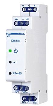
The OB-215 is a single-channel configurable digital input-output module with built-in RS-485 Modbus RTU communication. It is not a multi-channel rack I/O card. It is not a standalone controller. It is a deliberately minimal, low-cost building block designed to be deployed in quantity — one module per measurement point or small cluster — mounted in a local junction box close to the field, then networked back to a PLC, SCADA gateway or any Modbus RTU master over a single daisy-chained RS-485 cable.
That architecture shift — from star-wired analogue signals to bus-networked digital nodes — is what makes the OB-215 economically viable on large sites. At Rs. 4,375 per unit (ex-GST), deploying fifteen modules costs less than the cable and conduit for running fifteen individual 4–20 mA loops across a 300-metre process bay.
Buy OB-215 on Intelli-ElectroSignal Types the OB-215 Accepts — The Engineering Detail
The configurable sensor input is the key to the module's versatility. Depending on how the module is configured, the single input channel accepts:
- DC voltage transducer input: 0–10 V — standard output from many level transmitters, pressure transducers and flow signal conditioners used in process plants. Input impedance is high enough to avoid loading the transmitter.
- DC current transducer input: 0–20 mA — the dominant industrial standard for process signals. Covers 4–20 mA live-zero convention used on HART-compatible field instruments. The module handles the current-to-digital conversion internally.
- NTC 10 kΩ thermistor — suitable for ambient and equipment surface temperature monitoring where high precision is not required but low cost is essential.
- PTC 1000 / PT 1000 RTD — the standard platinum resistance temperature detector used in process industry temperature measurement. PT 1000 offers better noise immunity than PT 100 over long cable runs, relevant in electrically noisy plant environments.
- DS18B20 digital temperature sensor — one-wire digital sensor, ideal for distributed temperature monitoring where the sensor itself digitises the reading, eliminating analogue signal degradation on long runs.
- Pulse counter with non-volatile memory — accepts contact closure or open-collector pulse outputs from turbine flow meters, oval gear meters and positive displacement meters. The pulse count is retained in memory through power loss, which is critical for custody-transfer or batch-total applications.
- RS-485 to UART (TTL) interface converter mode — allows the module to act as a transparent serial bridge for integrating legacy instruments with TTL serial outputs into a Modbus network.
The output side is a relay output rated to switch up to 8 A, suitable for controlling small solenoid valves, alarm sounders, pilot lights or motor starters through interposing relays in oil and gas control panels.
Power Supply and Physical Characteristics
The OB-215 operates from a 12–24 V DC supply, compatible with the 24 V DC instrument power rails that are standard in hazardous-area junction boxes and marshalling cabinets across the Indian process industry. Power consumption is low — the module is designed for always-on monitoring duty in remote locations where supply capacity may be limited (battery-backed or solar-powered RTU enclosures, for example).
The module mounts on a standard 35 mm DIN rail, occupies minimal panel space, and the terminal block layout is designed for straightforward field wiring by instrument technicians without specialist tooling.
How RS-485 Modbus RTU Topology Works in Practice
RS-485 is a differential signalling standard. The bus carries two conductors — typically labelled A and B (or D+ and D−) — and communicates by measuring the voltage difference between them rather than an absolute voltage to ground. This differential nature gives RS-485 its characteristic immunity to common-mode noise: the electromagnetic interference that couples equally onto both conductors cancels out at the receiver. In a refinery with large rotating machines, VFDs and high-current power cables running parallel to instrument cable trays, this noise immunity is not a convenience feature — it is a fundamental requirement.
A single RS-485 segment can address up to 32 standard-load devices (more with repeaters) and carry data over distances up to 1,200 metres at lower baud rates. In practical OB-215 deployments, the recommended topology is a daisy-chain (trunk-and-drop) from the Modbus master at the control panel to each successive module in the field. Each OB-215 has a unique Modbus slave address configured at commissioning, so the master can poll each module individually for its input value and issue relay commands independently.
Termination resistors (typically 120 Ω) must be fitted at both physical ends of the RS-485 bus — at the master port and at the last slave module in the chain — to suppress signal reflections at high baud rates. Failure to terminate correctly is the most common commissioning fault in RS-485 networks and manifests as intermittent communication errors that are difficult to diagnose without a bus analyser.
OB-215 Specification Summary
| Parameter | OB-215 Specification |
|---|---|
| Channels | 1 configurable sensor input + 1 relay output |
| Power Supply | 12–24 V DC |
| Voltage Input Range | 0–10 V DC |
| Current Input Range | 0–20 mA DC |
| Temperature Sensors | NTC 10 kΩ, PTC 1000, PT 1000, DS18B20 |
| Pulse Counter | Yes, with non-volatile memory |
| Relay Output Switching Current | Up to 8 A |
| Communication | RS-485 Modbus RTU (built-in) |
| Additional Mode | RS-485 to UART (TTL) interface converter |
| Mounting | 35 mm DIN rail |
| Price (ex-GST) | Rs. 4,375 per unit |
| Brand / Origin | Novatek Electro — Made in India |
Quick Selection Guide — Application vs Module
| Application | Signal Type Used | OB-215 Mode | Price (ex-GST) |
|---|---|---|---|
| Tank level monitoring (4–20 mA transmitter) | 0–20 mA current loop | Current transducer input | Rs. 4,375 |
| Pipeline flow totalization (turbine meter) | Pulse / contact closure | Pulse counter with NV memory | Rs. 4,375 |
| Heat exchanger skin temperature | PT 1000 RTD | PT 1000 temperature input | Rs. 4,375 |
| Alarm aggregation from field contacts | Dry contact / voltage signal | Voltage input (0–10 V) or pulse | Rs. 4,375 |
| Remote solenoid / alarm relay control | Modbus coil write from SCADA | Relay output (8 A) | Rs. 4,375 |
| Legacy serial instrument integration | UART TTL serial | RS-485 to UART bridge mode | Rs. 4,375 |
Wiring Best Practices for Process Plant Environments
Cable Selection for RS-485 Bus
Use twisted-pair shielded cable (Belden 9842 equivalent or IS 694-compliant multi-core shielded instrument cable) for the RS-485 bus. Characteristic impedance should match the 120 Ω termination. Ground the shield at one end only — at the control panel end — to avoid creating ground loops that introduce noise on the differential bus. In hazardous classified areas, observe the applicable IS/IEC 60079 requirements for cable entry, gland sealing and earthing before installing any module or junction box.
Power Supply Wiring
Power each OB-215 from the 24 V DC instrument bus via a local fuse or MCB rated to protect the cable (typically 1 A per module). In remote RTU enclosures, use a dedicated 24 V DC SMPS with sufficient headroom for the full installed module count plus sensor excitation current. Verify that the supply voltage at the most remote module remains within the 12–24 V DC window under full load — voltage drop on long DC supply runs is a common oversight.
Analogue Signal Wiring
For 4–20 mA loops, use individually shielded twisted pairs routed in a dedicated instrument cable tray, segregated from power cables by the minimum separation specified in IS 1646 or IEC 61000-5-2. Keep loop lead resistance low and within the transmitter's load compliance specification. For PT 1000 inputs, use three-wire or four-wire RTD connections where cable resistance must be compensated — check the OB-215 connection diagram for the specific wiring configuration supported.
Troubleshooting Common Installation Issues
Intermittent Modbus Communication Faults
The most frequent field complaint. Root causes in order of probability: missing or incorrect termination resistors; mixed cable types with different characteristic impedances on the same segment; ground loops from shield grounded at multiple points; excessive stub lengths on branch drops; baud rate or parity mismatch between master and slave. Diagnose with a Modbus analyser or oscilloscope across the A/B terminals at the point of failure before replacing hardware.
Erratic Analogue Readings
Typically caused by induced noise from VFDs or power cables running parallel to the instrument cable. Solutions: increase physical separation, use a separate conduit, add ferrite cores at the module input terminals, or switch to a digital sensor type (DS18B20 or RS-485 native instrument) to eliminate analogue susceptibility entirely.
Relay Output Not Responding to Modbus Write
Verify that the correct Modbus coil register address is being written, the module slave address matches the master configuration, and the output is not inhibited by a local configuration parameter. Check relay coil voltage and contact continuity with a multimeter before concluding the relay has failed.
Why Novatek Electro?
- ISO 9001:2015 certified manufacturing — quality management system audited to international standard, ensuring consistent product quality across every batch.
- CE certified — electromagnetic compatibility and safety tested to European standards, reflecting a level of design rigour appropriate for industrial electrical environments.
- Made in India — Delhi-based manufacturer — local production means faster delivery, readily available spares and no import duty exposure on future procurement.
- 30+ years of electrical protection product experience — deep application knowledge in protection relays, monitoring devices and I/O modules for Indian industrial conditions.
- After-sales technical support — direct access to engineering support via email and phone for commissioning assistance, configuration guidance and warranty resolution.
The OB-215 is available at Rs. 4,375 per unit (ex-GST) through our authorised distribution channel. For project quantities of 10 units or more, contact our sales team for a project quotation including GST and logistics.
Buy on Intelli-Electro Email: sales@novatek-electro.in Call: +91-78400 54744